


Industrial processes often employ multiple data acquisition systems to monitor the health of assets and facility infrastructure. These systems can be either standalone or built as nodes within a larger automation topology.
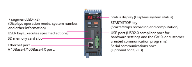
The GM10 is a scalable modular block I/O data acquisition system and data-logging platform that is designed for easy installation and maintenance and requires no programming. It supports remote web-based or wireless configuration and monitoring via Bluetooth connection. The unit can be DIN rail mounted, wall mounted or act as a standalone desktop application. The Yokogawa GM10 delivers industry leading reliability and measurement accuracy. In addition, a wide range of communication protocols guarantee compatibility with your network architecture.


* Creating predictive detection models and profile waveforms requires the Equipment/Quality Predictive Detection tool (sold separately).
By easily creating predictive detection models from past recorded OK/NG (Not Good) data and loading it into GM, you can detect prediction of abnormalities in manufacturing equipment and product quality degradation at an early stage. And because health scores which show the degree of normal and abnormal data consider correlations among multiple data to make determinations, they can capture prediction of abnormalities that are difficult for humans to detect.

|
Health monitor function empowers you to:
|
 |
By creating a profile waveform from past recorded data and loading it into GM, this waveform can be used as a threshold for process values. Profile waveforms are useful in applications where process values change over time. Also, you can see the deviation from the reference waveform on the screen.

|
Profile function empowers you to:
|
 |
By creating predictive detection model and profile waveform, Cloud or Offline Equipment/Quality Predictive Detection tool (paid separately) is required. To use cloud version, you need to apply from the following site to create an account.
*There are some functional restrictions during the free trial period.
*Search "OE10" on the member's site.
Note: Cloud version is available only for US, Canada, EU and UK.
Yokogawa's proprietary A/D converter allows the high speed module to measure data points as fast 1ms.
*With 1ch per module. At 2 ms, 2 ch per module, and at 5 ms or more, all 4 ch per module.
| Model | Scan interval | ||
|---|---|---|---|
| 1ms | 2ms | 10ms | |
| GM10-1 | 1ch | 5ch | 10ch |
| GM10-2 | 5ch | 25ch | 32ch |

Users have the ability to choose two different scan intervals on a single GM system. This allows users the flexibility to measure various types of inputs with two different scan intervals in a single system. For example, this provides for efficient, simultaneous measurement of signals with slow fluctuations such as temperature, and fast-changing signals such as pressure and vibration. Modules can be assigned to measurement groups.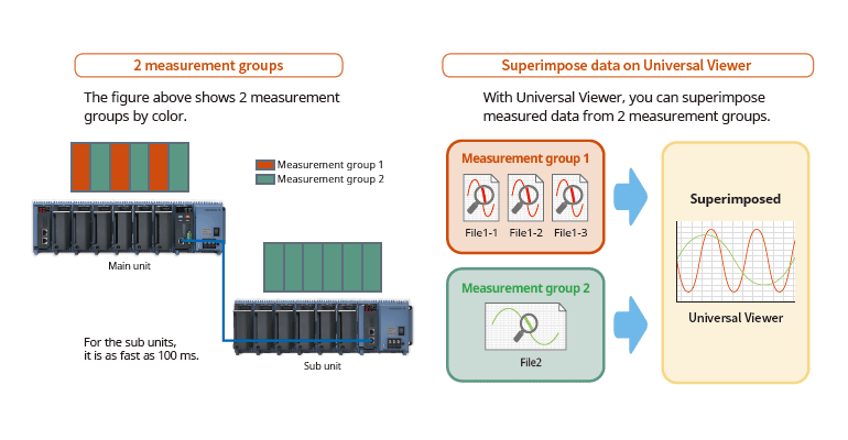
PID control functionControl function to enable PID and program control
|
 |
The web application enables remote operation and monitoring from a browser.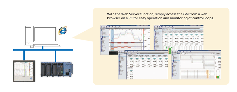
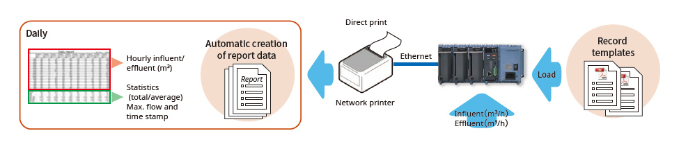
MATH function (/MT option)Supports various kinds of math computation, including basic math and functions (square root, logarithms, trigonometry). Write formulas using variables for measured or computed data and save or display the results—this saves time and effort on post-processing. Create hourly, daily, monthly, and other reports with the Report function. Event actionsAbility to assign actions tied to specific events during the operation of the data acquisition station. |
 |
Calibration correction schedule control function (/AH option)Schedule management for periodically executing calibration correction configuration and the like. You can set the input correction factor as a sensor correction factor and instrument correction factor. For AMS2750, we offer TUS software* that can easily create TUS (temperature distribution test) reports.* * For details on TUS software, consult with your Yokogawa dealer. Input calibration is performed in the AI channel setting screen, and the calibration period settings are entered in the schedule management setting screen. |
 |
Record pre-defined channel groups to separate data files with independent start and stop control. You can create up to 12 batches.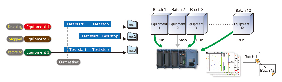

Comes standard with support for up to 100 ch of measurement (single-unit configuration)Up to 10 I/O modules can be linked to a single data acquisition module (GM10) |
Installs anywhereFor the desktop, DIN rails, or wall-mounting. No special attachments required.
 |
Select from a wide range of I/O modulesSelect modules according to your application. Noise-resistant, magnetic relay types also available. All modules have removable terminal blocks for easy wiring. The same modules used in the SMARTDAC+TM series. |
 |
| Model | Name | Measurement/Application | Channels |
|---|---|---|---|
| GX90XA-10-U2 | Analog input module | DC voltage, DC current (with external shunt resistor connected), thermocouple, RTD, contact (solid state relay scanner type) | 10 |
| GX90XA-10-L1 | DC voltage, DC current (with external shunt resistor connected), thermocouple, contact (Low withstand voltage solid state relay scanner type) | 10 | |
| GX90XA-10-T1 | DC voltage, DC current (with external shunt resistor connected), thermocouple, contact (electromagnetic relay scanner type) | 10 | |
| GX90XA-10-C1 | DC current (mA) (solid state relay scanner type) | 10 | |
| GX90XA-10-V1 | DC voltage, DC current (with external shunt resistor connected), thermocouple, contact (Solid state relay scanner type) | 10 | |
| GX90XA-04-H0 | DC voltage, DC current (with external shunt resistor connected), thermocouple, RTD, contact (individual A/D type) | 4 | |
| GX90XA-06-R1 | 4-wire RTD, 4-wire resistance(solid state relay scanner type) | 6 | |
| GX90YA | Analog output module | Current output (isolated between channels) | 4 |
| GX90XD | Digital input module | Remote control input or operation recording | 16 |
| GX90YD | Digital output module | Alarm output | 6 |
| GX90WD | Digital input/output module | Remote control input or operation recording/alarm output | DI:8/DO:6 |
| GX90XP | Pulse input module | Pulse signal data acquisition, integral count | 10 |
| GX90UT | PID control module | PID control (2 loop) | AI:2/AO:2 DI:8/DO:8 |
* For details on each module, refer to the general specifications.
You can also select modules using the convenient selection tool Product Finder.
Analog input module scan interval and measurement type
| Type | Channels | Scan interval (shortest) |
Scanner | TC | RTD | DCV | DI | mA | Resistance | Feature |
|---|---|---|---|---|---|---|---|---|---|---|
| Universal (-U2) | 10 | 100ms | SSR | √ | √ | √ | √ | Universal | ||
| Low withstand voltage relay (-L1) | 10 | 500ms | SSR | √ | √ | √ | Mid-price | |||
| Electromagnetic relay (-T1) | 10 | 1s | Relay | √ | √ | √ | Noise-resistance | |||
| DC current input (-C1) | 10 | 100ms | SSR | √ | mA only | |||||
| High withstand voltage (-V1) | 10 | 100ms | SSR | √ | √ | √ | High withstand voltage | |||
| High speed universal (-H0) | 4 | 1ms | — | √ | √ | √ | √ | High speed measurement | ||
| 4-wire RTD (-R1) | 6 | 100ms | SSR | √ | √ | 4-wireRTD |
Internal memory and max. I/O channels
| Type | Internal memory | Max. input/output channels* | |
|---|---|---|---|
| GM10-1 | 500 MB | Single-unit configuration | 0 to 100 |
| Multi-unit configuration | 0 to 100 | ||
| GM10-2 | 1.2 GB | Single-unit configuration | 0 to 100 |
| Multi-unit configuration | 0 to 420 | ||
| Input type | Measuring accuracy*1 (typical value*2) | |
|---|---|---|
| DCV | 20 mV | ±(0.01% of reading + 5 μV) |
| 60 mV | ±(0.01 % of reading +5 μV) | |
| 6 V (1-5V) | ±(0.01% of reading + 2 mV) | |
| TC*3 | R, S | ±1.1 °C |
| B | ±1.5 °C | |
| K (-200.0 to 1370.0°C) | ± (0.01% of rdg +0.2°C for 0.0 to 1370.0°C; ± (0.15% of rdg +0.2°C) for -200.0 to 0.0°C | |
| K (-200.0 to 500.0°C) | ± 0.2°C for 0.0 to 500.0°C; ± (0.15% of rdg +0.2°C) for -200.0 to 0.0°C | |
| J | ± 0.2°C for 0.0 to 1100.0°C; ± (0.10% of rdg + 0.2°C) for -200.0 to 0.0°C | |
| T | ± 0.2°C for 0.0 to 400.0°C; ± (0.10% of rdg + 0.2°C) for -200.0 to 0.0°C | |
| N | ± (0.01% of rdg + 0.2°C) for 0.0 to 1300.0°C; ± (0.22% of rdg + 0.2°C) for -200.0 to 0.0°C | |
| RTD | Pt100 (-200.0 to 850.0°C) | ±(0.02% of rdg + 0.2°C ) |
| Pt100 (-150.00 to 150.00°C) | ±(0.02% of rdg + 0.16°C ) | |
Expand up to 420 ch by using the GX90EX expansion module. (GM10-2)
On the GM10-2 large capacity type, up to 1000 ch are available for recording when including MATH and communication channels. Connect units with LAN cables for dispersed installations.
 You connect directly with a LAN cable without connecting through a hub or repeater.
Reduce wiring with distributed installationWhen the data logger is installed offsite (away from the DUT), you can place the sub unit at the site and monitor data without the need for long-distance wiring of thermocouples and other sensors. |
 |
Through a Web browser you can monitor the GM in real time and change settings. You can easily build a seamless, low-cost remote monitoring system with no additional software.
|
Real time monitoring With the scroll bar, you can seamlessly scroll between past and current trends |
 |
|
Enter settings online with a web browser The setting screen lets you copy AI channel settings and other information to Excel for editing. You can reimport the data into the setting screen after editing. |
 |
CENTUM/STARDOM communication package
The FTP client/server functions allow you to easily share and manage data from a centralized file server

The GM can send a variety of informative e-mail messages that include alarm notification reports, periodic instantaneous data values, scheduled report data and other information.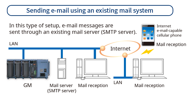
Automatic network setup (DHCP) functionUsing Dynamic Host Configuration Protocol (DHCP), the GM can automatically acquire the settings it needs (IP address) for network communications from a DHCP server. This makes i6t easier than ever to install the unit on a plant network. |
 |
Time synchronization with network time serversGM uses SNTP protocol in client mode to acquire time information from a network time-server. This function allows any number of GM units within a facility to have precisely synchronized time; all units will record data with coordinated date and time stamp information. In addition, GM can function as a server, providing time data to other SNTP client units on the network. |
 |
Supports long-duration and multichannel recording. Measured data is always stored to internal memory, and data is transferred to external storage media at regular intervals. Redundancy can be achieved by sending data to a server with the FTP client function. Securely saves measured data even in the event of a sudden power loss.
With an internal memory of 1.2 GB and recording interval of 1 sec. |
 |
Select file formats according to your applicationFor increased security, measured data can be saved in binary format. This format is very difficult to decipher or modify in traditional text editors or other programs. To enable easy and direct opening of the data in text editors or spreadsheet programs, choose text format. This allows you to work with your measurement data without dedicated software. |
 |
Security enhancementsSafely sends and receives customer data. |
Key lockYou can use settings to lock the GM10 operation keys in order to avoid accidental start/stop of measurement or computation. |
Analog front end moduleA proprietary A/D converter delivers high speed, high precision data acquisition. (High-speed AI, PID Control module)  |
Standards supportedConforms to various standards such as CSA, UL, CE / EMC Directive / CE / Constant Voltage Directive, European RoHS Directive, WEEE Directive, RCM, KC Mark (Korea)  |
| SMARTDAC+ GX /GP/GM advanced security function option (/AS) provides safe and traceable data management in applications such as pharmaceutical manufacturing, biotechnology, health management, and medical institutions. The advanced security function supports the strict requirements of US FDA 21 CFR Part 11, EU-GMP Annex 11 and other associated guidelines for data management. It also supports data integrity in accordance with ALCOA+ (Attributable, Legible, Contemporaneous, Original, Accurate, Complete, Consistent, Enduring, Available) mentioned in PIC/S, WHO, MHRA and FDA guidance documents. |
 |
What is "ALCOA +"?
It refers to A: attribution, L: legibility, C: simultaneity, O: originality, A: accuracy, C: completeness, C: consistency, E: Persistence, and A: Availability. ALCOA + is a requirement for data integrity guidelines of PIC / S (Pharmaceutical Testing Contract and Pharmaceutical Testing Joint Scheme), WHO (World Health Organization), MHRA (Pharmaceuticals and Drug Regulatory Authority: UK), and FDA (Food and Drug Administration).
Measured data, settings, and operation logs are saved to a single encoded binary file. Encoded data in binary format offers a high level of security because it cannot be opened in most text editors.
If the data files are damaged or tampered with, SMARTDAC+ Standard Universal Viewer software will identify the nonconformity and notify the user accordingly.
Security data file transferSMARTDAC+ can automatically transfer data to an FTP server. FTPS, which encrypts data transferred via FTP using SSL, is also supported, allowing data files to be transferred safely. |
 |
Electronic signature(data record signing) functionMeasurement data can be displayed and confirmed on the GX/GP (only the data in the internal memory) or the SMARTDAC+ Standard Universal Viewer software, and an electronic signature can be applied to that data. Three levels of signature are available: operator, supervisor and quality control. The signature along with information such as pass/fail and comments can be saved to the data for review and audit. |
 |
Data integrity requires that the right users have access to the right information.
SMARTDAC+ can create users with various access privileges.

The SMARTDAC+ operation log is saved to a file along with measurement data.
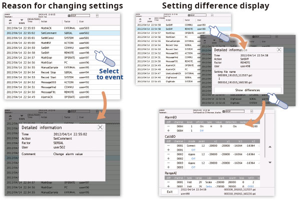
When settings are changed, it is possible to record the reason for the change along with the setting change operation. In addition, checking the details of setting changes from "setting difference operation history" makes greatly reduces the data checking work during audits.
SMARTDAC+ Standard Software is possible to display measurement data, display the operation log, and configure the GX/GP/GM. It is also possible to sign in data using the SMARTDAC+ Standard Universal Viewer.
The Universal Viewer software can display data files in various forms such as waveforms and numeric values. It can display and print not only measurement data but also alarm and message lists and operation logs. With the operation log, a comparison of the settings before the change and those after the change can be displayed, allowing you to check the changes in detail.
It is also possible to sign the data by entering the user name, user ID and password after confirming the measurement data. If the data has already been signed, you can sign at a different level after confirming the signature state on the screen.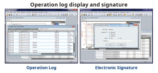
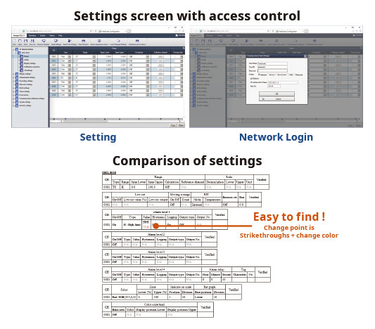
Hardware Configurator software allows for offline system configuration which can be imported via SD memory or external storage media as well as Ethernet communication. System settings can be printed in a table format to support GX /GP/GM system validation (IQ/OP/PQ).
In addition, a pair of selected setup data files can be compared, and their differences can be displayed and printed in table format.
Validation documentation (sold separately) is a validation protocol template that simplifies GX/GP/GM and SMARTDAC+ Standard system validation. The document is provided on the Yokogawa website as an MS Word file for easy editing.*
*The validation and document verification are the customer’s responsibility.


